
HIGHWAY GUARDRAILS
W-Beam Guardrail
A two-corrugation steel beam for roadside and median guardrail systems. Review the structure, choose the required finish and dimensions, and send your project drawing for quotation.
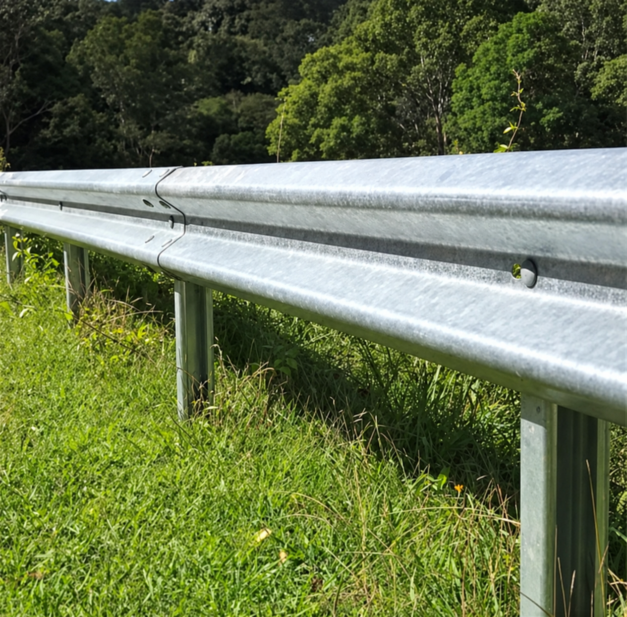 Installed W-Beam · application reference

Galvanized · W-Beam Guardrail
The photograph shows a galvanized W-Beam example. Confirm the selected finish and panel drawing for your project.
The image shows an installed example. Quoted panel size, post layout and surface finish follow the confirmed project drawing.
BUILD YOUR REQUEST
Configure your W-Beam guardrail
01 Surface finish or OEM
02 Panel thickness mm · confirm by drawing
03 Steel grade confirm by drawing
Your choices will be added to the enquiry form automatically. You can attach the project drawing there.
Product overview
TWO-CORRUGATION PROFILE
A beam, posts and connections working as one system.
W-Beam guardrails use a corrugated steel panel connected to support posts. When a vehicle contacts the barrier, the beam and posts may deform as part of the complete installed system. The specified panel, post spacing, foundation and end treatment must be considered together for each project.
Description adapted from the supplied W-Beam product manual; performance depends on the complete approved system.
How W-Beam guardrails work
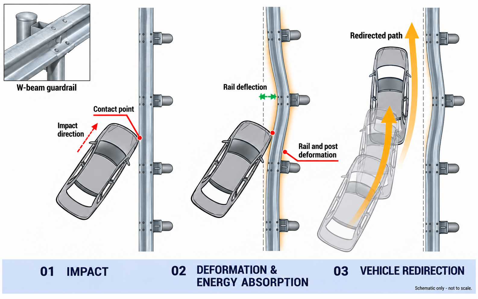
IMPACT / DEFORMATION / REDIRECTION
How force passes through the system
When a vehicle contacts the W-Beam rail, the panel can bend and transfer load through its connections to the posts and foundation. The complete approved system may help redirect the vehicle along the barrier.
Concept illustration only. It is not a crash-test result or a performance rating; actual performance depends on the tested system and installation conditions.
Open full-size diagram ↗Installation & assembly reference
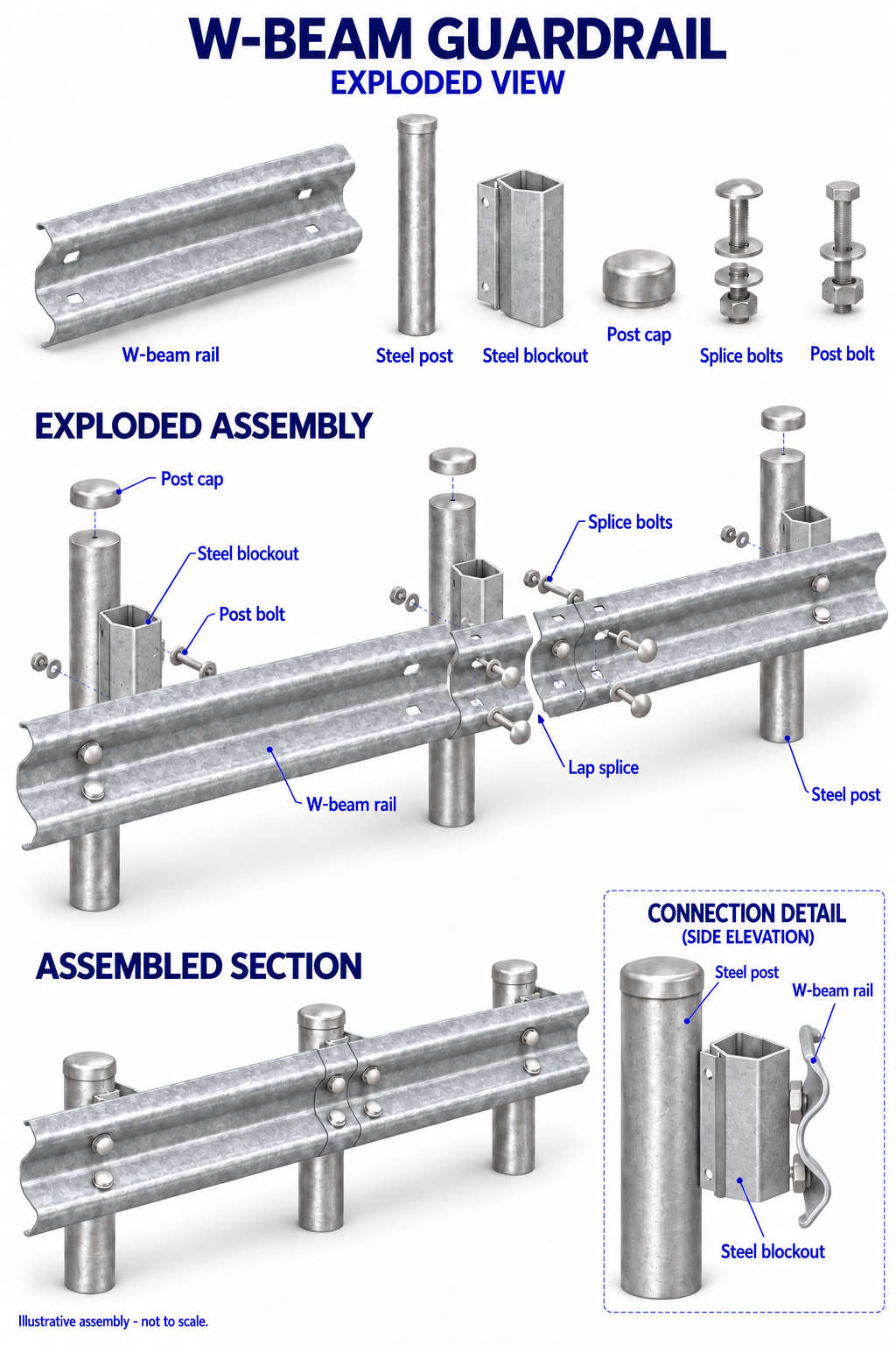
RAIL / BLOCKOUT / POST / FASTENERS
See how the main parts connect.
The supplied illustration shows the rail panel connected to steel posts through blockouts, with overlapping panels fixed by splice bolts. Post bolts and caps complete the shown assembly.
- Confirm the approved layout, post locations and foundation details.
- Set posts and attach the specified blockouts.
- Position and overlap the W-Beam panels, then install the specified fasteners.
- Check alignment, connection details and end treatment against the project drawing.
The illustration explains the assembly, not the full site installation procedure. Final sequence, bolt torque, foundation and end treatment must follow the approved project documents.
W-Beam models & specifications
Each P-DB panel model is listed below with its dimensions and use. The P prefix is our display code for the corresponding DB model in GB/T 31439.1—2025. Dimensions are millimetres; confirm the selected hole pattern by project drawing.
| PIPESD model | Panel length | Width | Wave height | Thickness | Use |
|---|---|---|---|---|---|
| P-DB00 | 8,320 | 310 | 85 | 2 / 2.5 / 3 / 4 | Extended panel |
| P-DB01 | 4,320 | 310 | 85 | 2 / 2.5 / 3 / 4 | Standard panel |
| P-DB02 | 3,820 | 310 | 85 | 2 / 2.5 / 3 / 4 | Adjustment panel |
| P-DB03 | 3,320 | 310 | 85 | 2 / 2.5 / 3 / 4 | Adjustment panel |
| P-DB04 | 2,820 | 310 | 85 | 2 / 2.5 / 3 / 4 | Adjustment panel |
| P-DB05 | 2,320 | 310 | 85 | 3 | Standard panel |
| P-DB05 | 2,320 | 310 | 85 | 2 / 2.5 / 4 | Adjustment panel |
| P-DB06 | Under 2,320* | 310 | 85 | 2 / 2.5 / 3 / 4 | Adjustment panel |
* P-DB06 length is determined by the project design. P-DB05 is a standard panel at 3 mm; the other listed thicknesses are adjustment panels. These codes describe models, not stock availability.
Base steelCarbon structural steel meeting at least the Q235-grade requirements of GB/T 31439.1—2025; Q345 by project specification.
Surface finishHot-dip galvanized / powder-coated / galvanized + powder-coated. Confirm the coating system and requirements against the project drawing.
Components & supply details
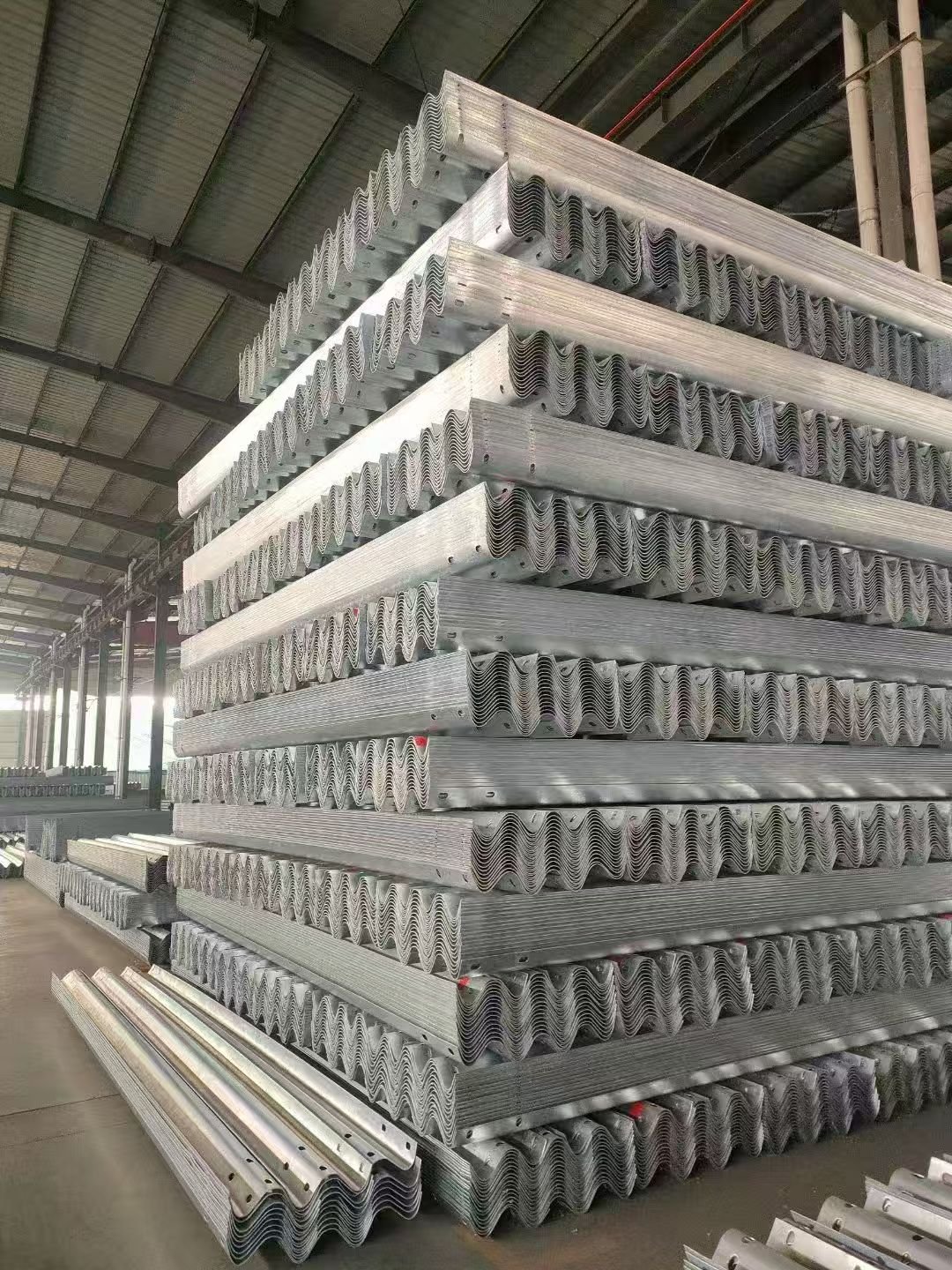
PANELS / POSTS / CONNECTIONS
Specify the complete supply scope.
A W-Beam order may include panels, posts, end terminals, brackets or blockouts, splice bolts and connecting bolts. Tell us which components you need and provide the matching drawing so hole patterns, lengths and surface finish can be checked together.
- Panel model and thickness
- Post section and spacing
- Connection hardware and end treatment
- Galvanizing, coating or drawing-based finish
Stock image for product reference; the exact supplied components depend on the agreed order.