HIGHWAY GUARDRAILS
Hot-Dip Galvanized + Powder-Coated Guardrail
Choose a W-Beam or Thrie-Beam panel with hot-dip galvanizing and a powder-coated finish. Specify panel thickness, steel grade and color against your project drawing.
 Blue W-Beam · coated appearance reference

Hot-dip galvanizing + powder coating · W-Beam Guardrail
Blue W-Beam coating appearance; underlying galvanizing is not verified from a photo.
Photographs are visual references only; neither verifies the complete two-layer coating system.
BUILD YOUR REQUEST
Configure your guardrail
01 Beam profile
02 Panel thickness mm · confirm by drawing
2.0 and 2.5 mm are listed for W-Beam only; the supplied Thrie-Beam reference lists 3.0 and 4.0 mm.
03 Steel grade confirm by drawing
04 Project color optional
Provide the approved color sample or drawing on the enquiry page.
Your selected profile, thickness, grade and color reference will be added to the enquiry automatically.
Product overview
PROFILE + SURFACE FINISH
Choose the beam profile, then confirm the finish.
This finish combines hot-dip galvanizing with a powder-coated surface on the specified guardrail parts. Choose the two-wave W-Beam or three-wave Thrie-Beam profile first; color and coating requirements are then defined by the project documents.
Blue W-Beam coating appearance; underlying galvanizing is not verified from a photo. Photographs are visual references only; neither verifies the complete two-layer coating system.
How the guardrail works
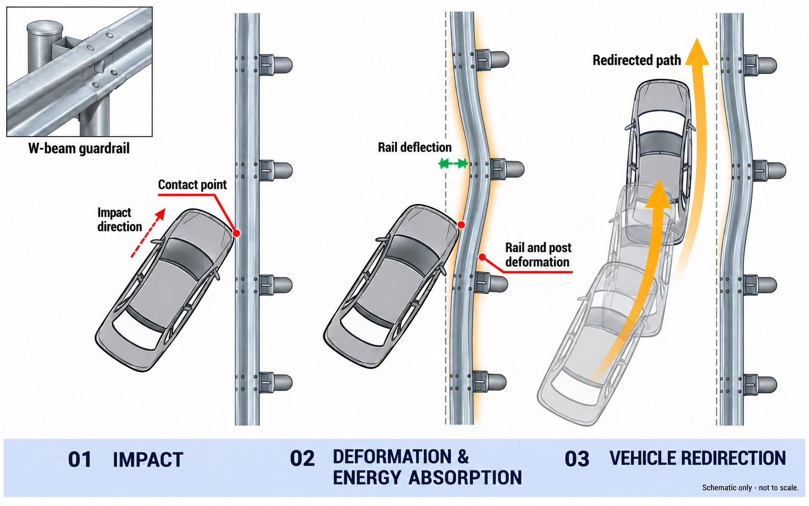
TWO-WAVE SYSTEM REFERENCE
W-Beam: rail deflection and vehicle redirection
The supplied W-Beam diagram shows vehicle contact, rail-and-post deformation and redirection as one system response. The surface finish does not define the impact performance.
W-Beam concept only; not a crash-test result or a stated containment level. Check the approved system and installation drawing for project performance.
Open full-size diagram ↗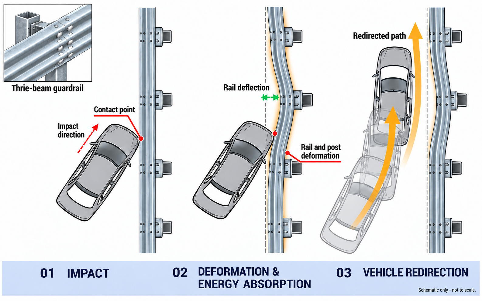
THREE-WAVE SYSTEM REFERENCE
Thrie-Beam: load passes through the complete system
For the three-wave profile, contact loads move through the beam, connections, posts and foundation. The installed system may deform and help guide the vehicle along the barrier.
Three-wave concept reference only; not a crash-test result or a stated containment level. Check the approved system and installation drawing for project performance.
Open full-size diagram ↗Installation & assembly reference
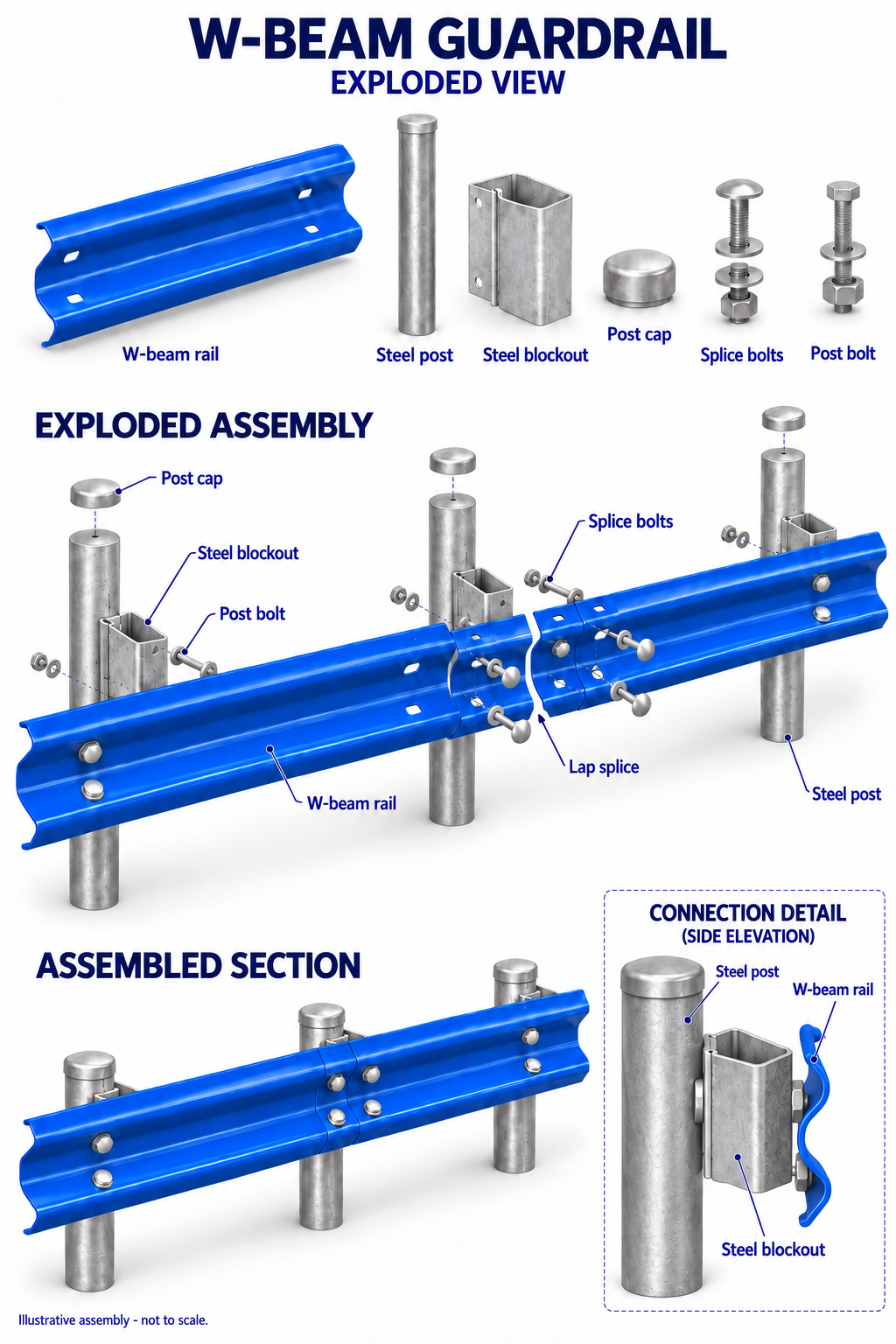
TWO-WAVE ASSEMBLY REFERENCE
W-Beam rail, post and blockout
The two-wave assembly reference identifies the rail, steel post, blockout, splice bolts and post bolts. Confirm the overlap direction, hole pattern and end treatment on the approved drawing.
- Confirm the selected panel model, thickness, length and hole pattern.
- Match the posts, blockouts, foundations and spacing to the system drawing.
- Install the specified splice and post connections and check end treatment.
- Inspect the supplied surface finish against the agreed project specification.
The blue panel depicts the powder-coated appearance only; the drawing does not verify the underlying galvanizing specification. The final installation sequence is determined by the approved project documents.
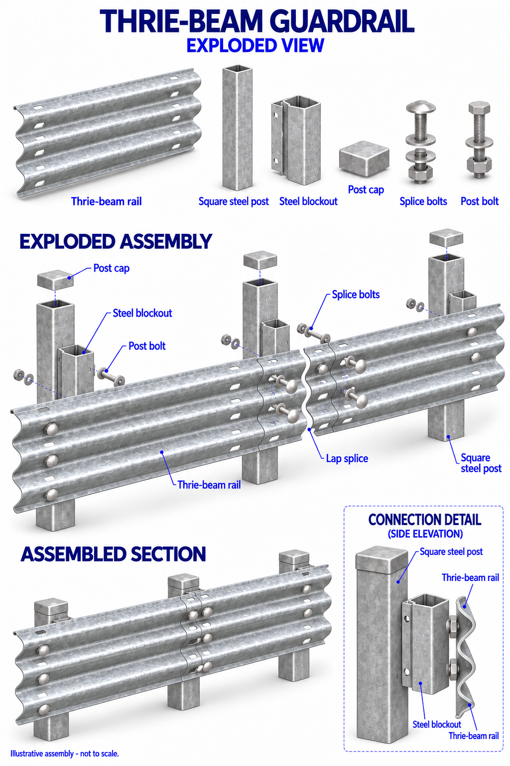
THREE-WAVE ASSEMBLY REFERENCE
Thrie-Beam rail with square hollow posts
The three-wave concept shows a panel splice and matching blockouts at square hollow posts. The P-RTB “-1” models correspond to the square-post arrangement; “-2” models use a pipe or H-section post alternative.
- Confirm the selected panel model, thickness, length and hole pattern.
- Match the posts, blockouts, foundations and spacing to the system drawing.
- Install the specified splice and post connections and check end treatment.
- Inspect the supplied surface finish against the agreed project specification.
This assembly illustration shows structure, not the selected surface finish. Exact holes, fasteners and coating follow the approved drawing. The final installation sequence is determined by the approved project documents.
Models & specifications
The surface finish does not create a new panel shape or model number. All individual W-Beam and Thrie-Beam panel entries below retain their PIPESD display codes and standard-based dimensions. Choose the matching profile and model, then confirm coating, holes and connections from the project drawing. Dimensions are millimetres.
W-Beam panel models two-wave profile · GB/T 31439.1—2025
| PIPESD model | Panel length | Width | Wave height | Thickness | Use |
|---|---|---|---|---|---|
| P-DB00 | 8,320 | 310 | 85 | 2 / 2.5 / 3 / 4 | Extended panel |
| P-DB01 | 4,320 | 310 | 85 | 2 / 2.5 / 3 / 4 | Standard panel |
| P-DB02 | 3,820 | 310 | 85 | 2 / 2.5 / 3 / 4 | Adjustment panel |
| P-DB03 | 3,320 | 310 | 85 | 2 / 2.5 / 3 / 4 | Adjustment panel |
| P-DB04 | 2,820 | 310 | 85 | 2 / 2.5 / 3 / 4 | Adjustment panel |
| P-DB05 | 2,320 | 310 | 85 | 3 | Standard panel |
| P-DB05 | 2,320 | 310 | 85 | 2 / 2.5 / 4 | Adjustment panel |
| P-DB06 | Under 2,320* | 310 | 85 | 2 / 2.5 / 3 / 4 | Adjustment panel |
P-DB is our display prefix. DB05 appears twice because its standard-panel and adjustment-panel thickness rules differ. DB06 length follows the project design. The model list does not imply stock availability.
Thrie-Beam panel models three-wave profile · GB/T 31439.2—2025
| PIPESD model | Panel length | Width | Wave height | Thickness | Post / use |
|---|---|---|---|---|---|
| P-RTB00-1 | 8,320 | 506 | 85 | 4 | Square post · extended |
| P-RTB01-1 | 4,320 | 506 | 85 | 4 | Square post · standard |
| P-RTB02-1 | 3,320 | 506 | 85 | 4 | Square post · standard |
| P-RTB03-1 | 2,320 | 506 | 85 | 4 | Square post · adjustment |
| P-RTB04-1 | Under 2,320* | 506 | 85 | 4 | Square post · adjustment |
| P-RTB00-2 | 8,320 | 506 | 85 | 3 / 4 | Pipe / H post · standard |
| P-RTB01-2 | 4,320 | 506 | 85 | 3 / 4 | Pipe / H post · standard |
| P-RTB03-2 | 2,320 | 506 | 85 | 3 / 4 | Pipe / H post · adjustment |
| P-RTB04-2 | Under 2,320* | 506 | 85 | 3 / 4 | Pipe / H post · adjustment |
P-RTB is our display prefix. The five “-1” entries suit square posts and specify 4 mm panels; the four “-2” entries suit steel pipe or H-section posts and allow 3 or 4 mm as listed. RTB04 adjustment length follows project design. The model list does not imply stock availability.
Base steelCarbon structural steel meeting at least Q235-grade requirements under the applicable panel standard; Q345 when specified for the project.
Surface finishHot-dip galvanizing + powder coating. Specify galvanizing, powder coating, surface preparation, color and acceptance criteria in the approved project documents.
Color referenceProvide the approved code, sample or project drawing.
Components & supply details
Specify the matching panel, posts, blockouts or brackets, splice bolts, post bolts and end treatment together according to the approved barrier system.
- Profile and model: W-Beam P-DB or Thrie-Beam P-RTB entry
- Geometry: panel length, thickness, hole pattern and post spacing
- Finish: Confirm which panels and connection parts receive galvanizing and powder coating, including color.
- Drawing: confirm connections, foundations and end treatment
The assembly diagrams above are profile-specific references. Exact coating layers, matching accessories and supply quantities require confirmation before quotation.