Formed steel sections
Confirm section depth, flange, lip and wall thickness for each structural member.
SOLAR MOUNTING / PRODUCT DETAIL
Project-based steel support structures for solar panels. Select the required supply scope, then confirm members and connections from your drawings.
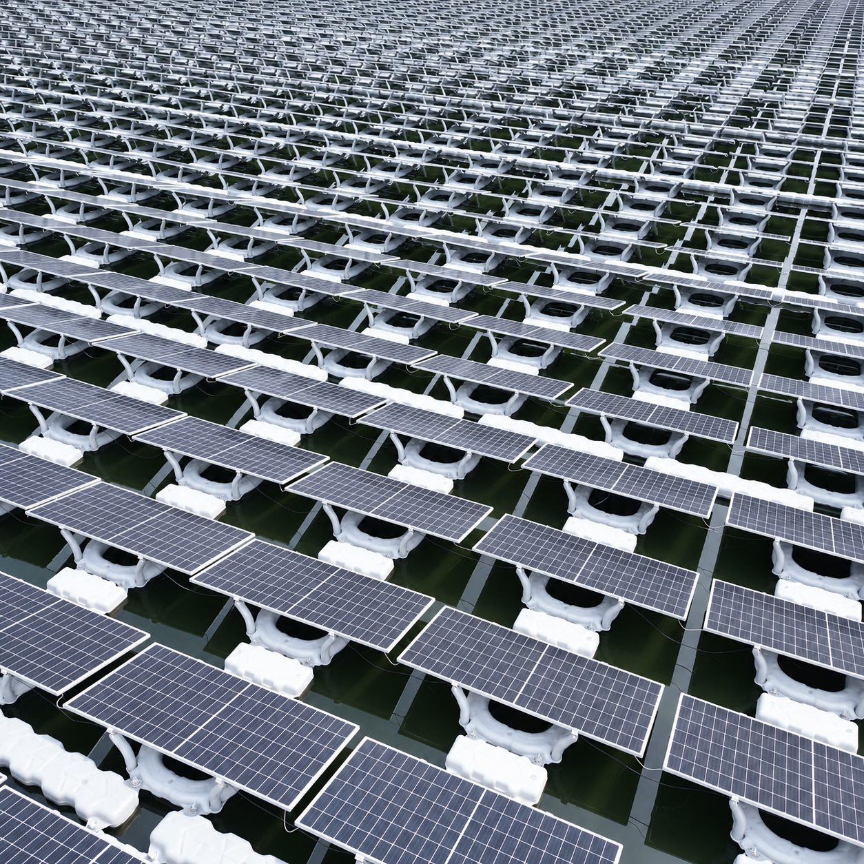
Mounting layout and steel components are confirmed from project drawings.
01 / PRODUCT OVERVIEW
Solar mounting structures hold photovoltaic panels in the position required by a project. Posts, rails, braces and connection parts work together as an assembly. Depending on the drawing, formed C-channel steel may be used for selected support members.
PROJECT-BASED SUPPLY
The order may cover a complete support assembly, selected steel members or parts made to drawings. The drawings define panel layout, member sections, connection points, surface finish and quantities.
Use the selection box above to describe the required supply scope. The quotation confirms which components are included.
02 / APPLICATIONS
Ground installations, roof-mounted arrays and other site layouts require different support geometry and connections. These examples show how the mounting structure can be arranged for different sites; the approved drawing defines the actual project.
The structure illustration also depicts electrical or drive equipment. Those items are not included unless they appear in the confirmed supply list.
03 / PRODUCT DETAILS
Each steel member must meet the same project drawing for section geometry, cut length, hole pattern, material grade and finish. These details determine how posts, rails and braces fit together in the completed solar mounting structure.
Confirm section depth, flange, lip and wall thickness for each structural member.
Slot shape, hole spacing and member length follow the approved fabrication drawing.
Specify steel grade, wall thickness and surface protection in the project documents.
Posts, rails, braces and fasteners are checked together against the mounting layout.
The images explain product form and processing. Exact dimensions, material grade and coating are confirmed for each order.
04 / PRODUCTION EQUIPMENT
Profile forming equipment and production lines shape the steel members. Member shape, cut length and hole layout are checked from the approved drawing before processing.
05 / ACCESSORIES
Brackets, base plates and connecting pieces join the support members. The photo shows possible forms; part shape, hole pattern and quantity must match the project assembly drawing.
Confirm the interface between posts, rails, braces and panel supports. The supply list states the required fasteners and connection parts, so a member-only order is not mistaken for a complete structure.
Return to project selection ↑06 / PRODUCTION PROCESS
Roll forming, hole punching, surface treatment and inspection are shown as production references. The actual process route and acceptance checks are set by each order's drawings and specification.
07 / STOCK & DELIVERY
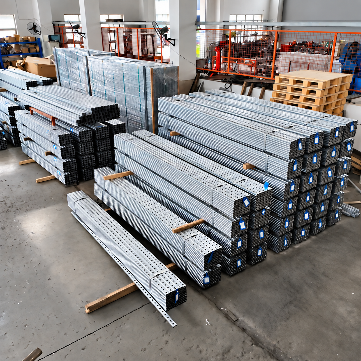
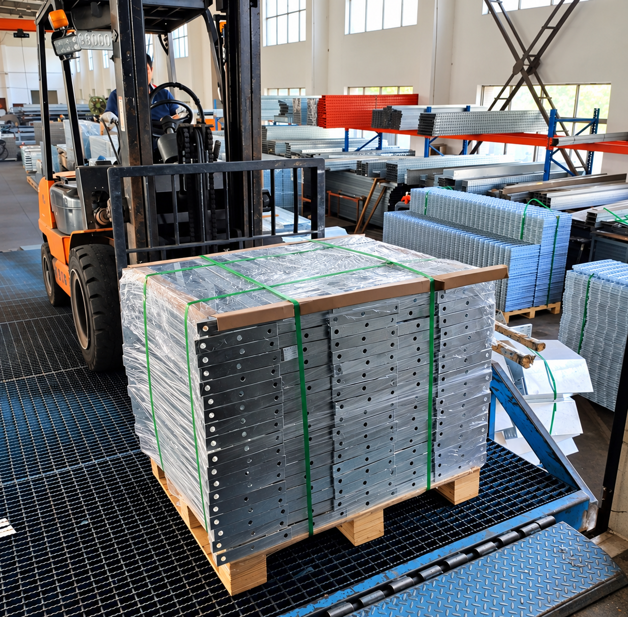
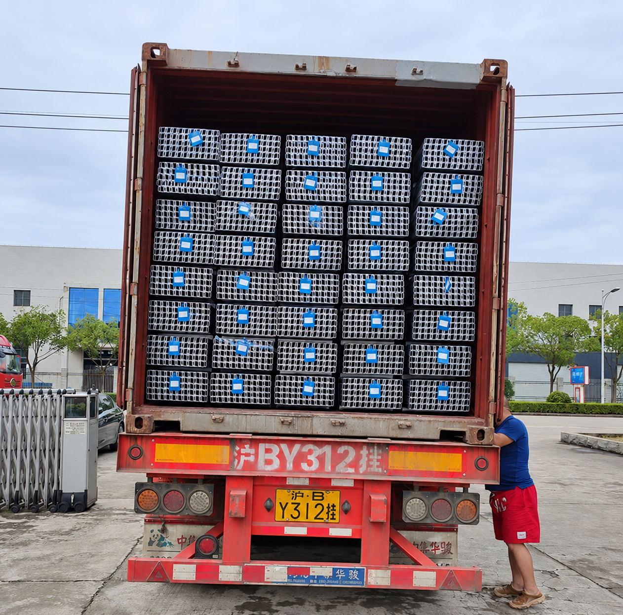
Finished members are grouped for storage, forklift handling and container loading. Bundle marks, protective packing and the loading plan are confirmed for each order.
08 / QUESTIONS
These details help us review the scope of a solar mounting order.
Send the section, length and hole-position drawings with the required quantity. Manufacturing feasibility and tolerances are reviewed before quotation.
Only if the agreed supply list includes it. Posts, rails, braces, brackets, clamps and fasteners are confirmed in the quotation and bill of materials.
Share the array layout, member and connection drawings, installation conditions, material and finish requirements, and estimated quantity.