01
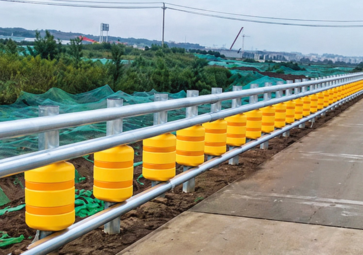
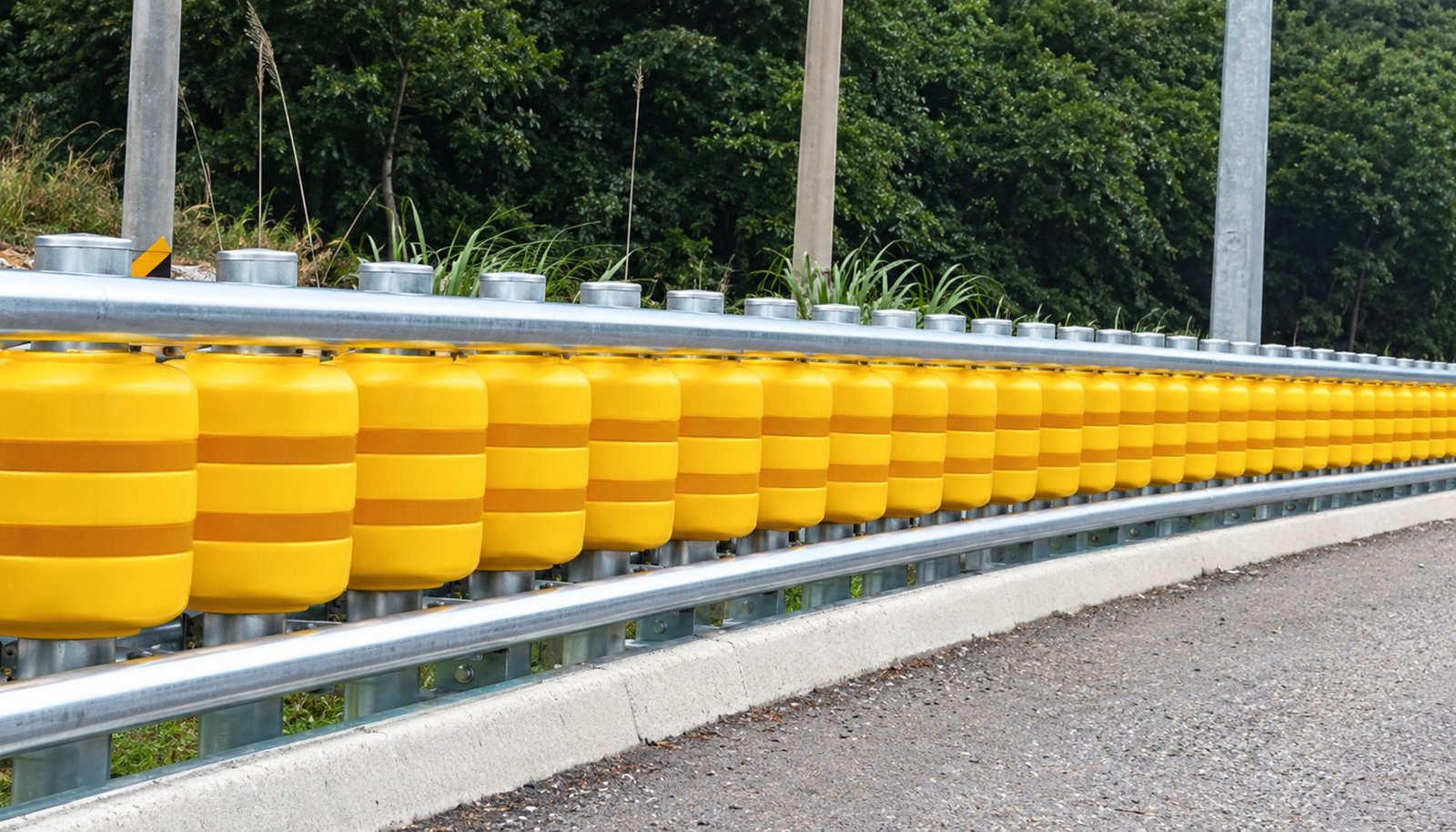
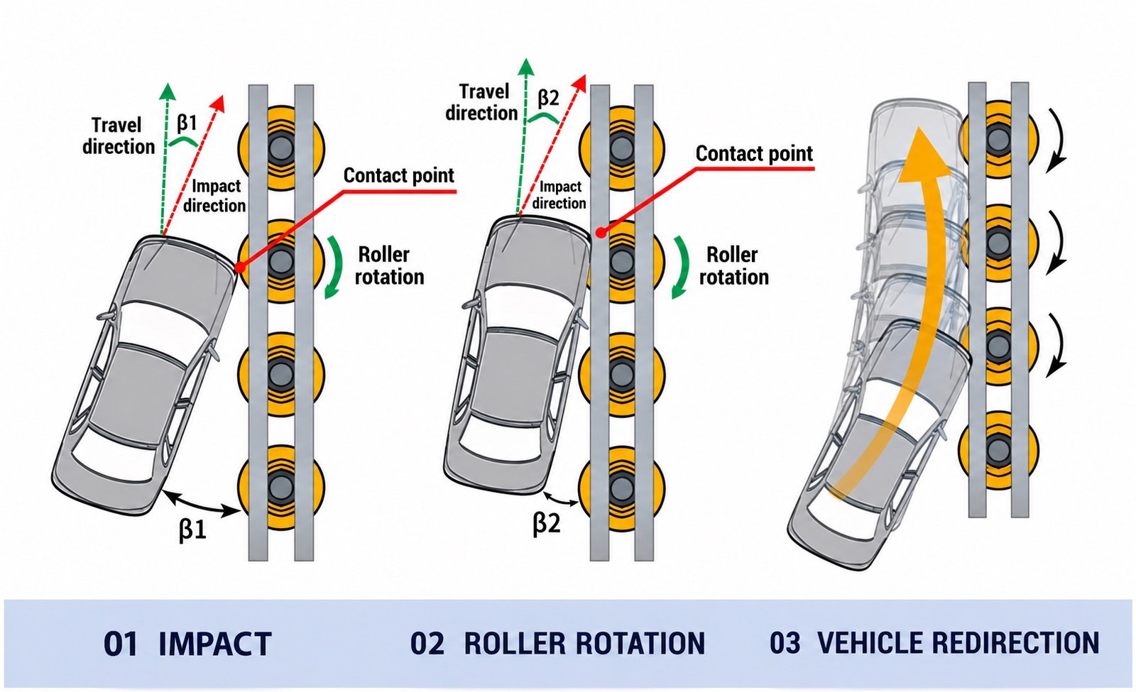
Rails and posts form the supporting barrier system.

Rails and posts form the supporting barrier system.
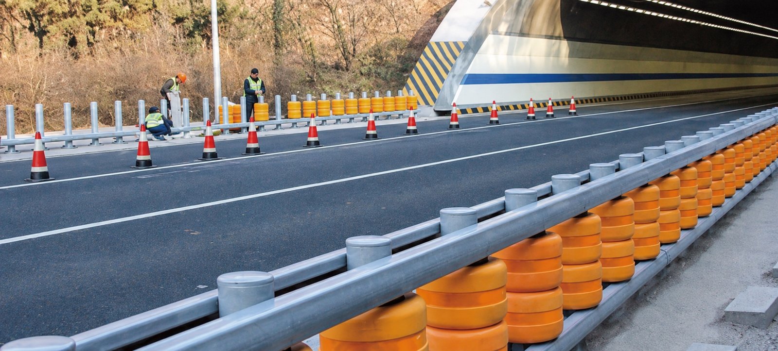
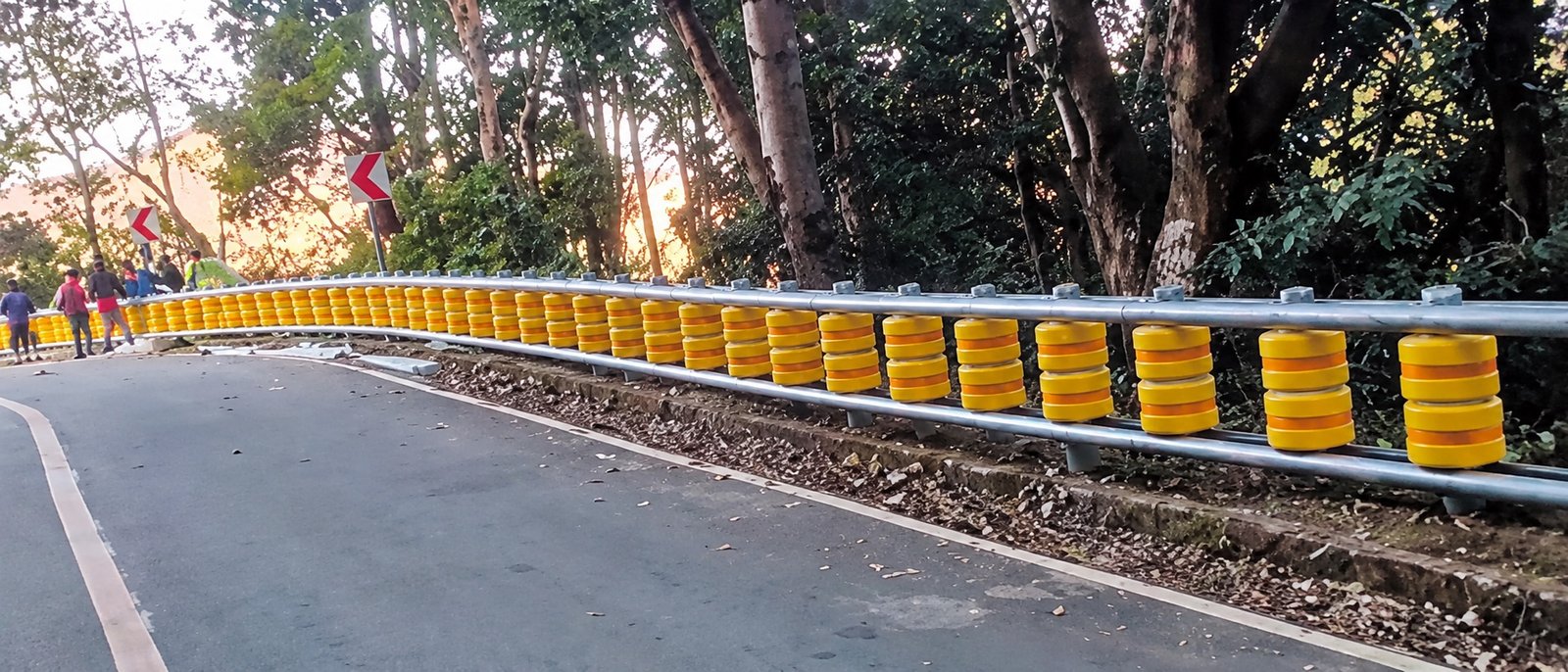
The rollers are designed to rotate when contacted; the complete system guides the vehicle along the barrier.
Actual performance depends on the system and installation. Refer to applicable test reports and project requirements.
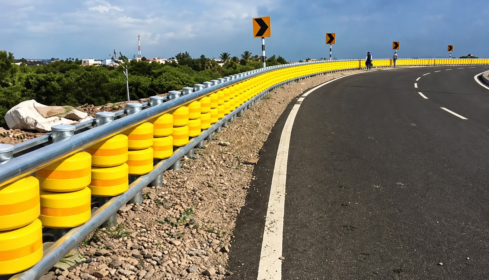
Roller barrier systems combine rotating rollers with steel rails, posts and connection components. Select a complete system, individual rollers, or posts and accessories above, then send your drawings for a project-specific quotation.
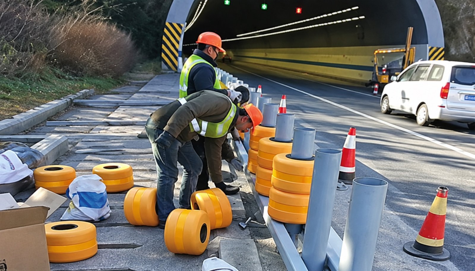
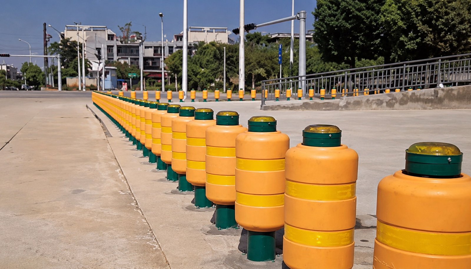
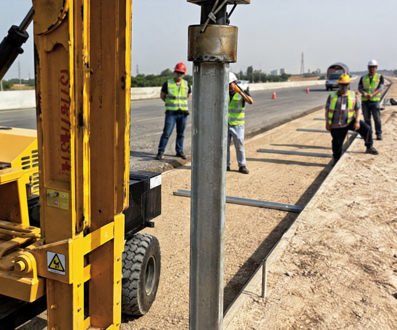
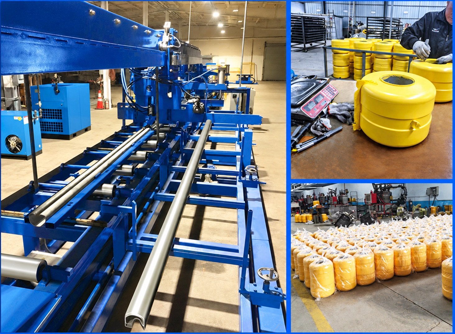
The images below show the supplied components, assembly sequence and road applications. Final configuration is checked against your approved project drawings.
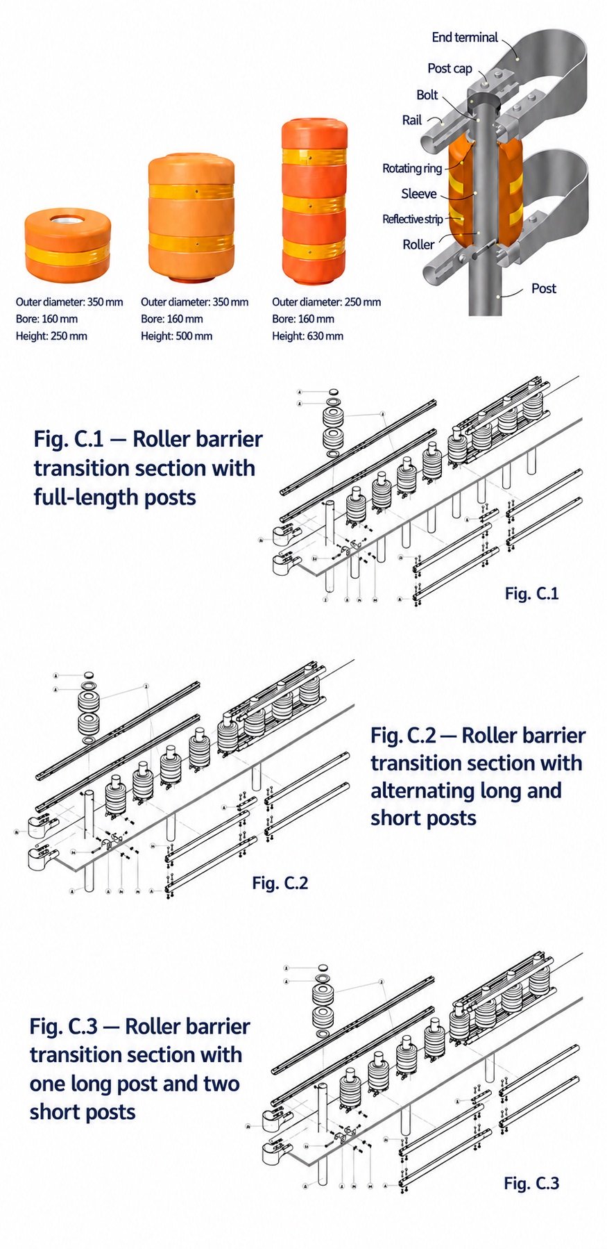
Reference roller sizes are transcribed from the supplied illustration. Confirm every dimension and component against the approved drawing before ordering.
| Illustrated roller | Outer diameter (mm) | Bore diameter (mm) | Height (mm) |
|---|---|---|---|
| A | 350 | 160 | 250 |
| B | 350 | 160 | 500 |
| C | 250 | 160 | 630 |
| Rails, posts, fixings, material and finish | Specify on the project drawing | ||
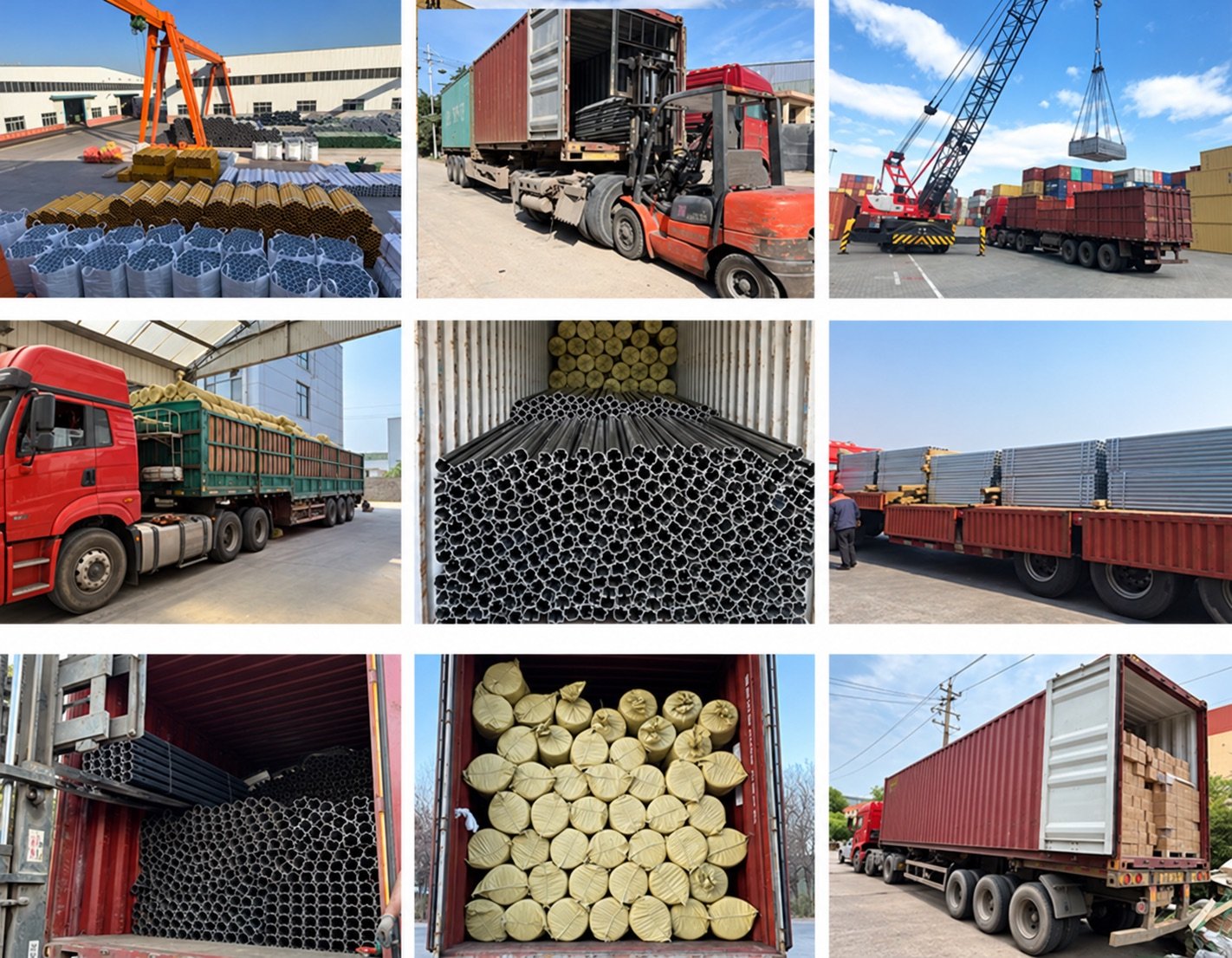
Application reference images edited from the supplied collage. Project names and locations are not assigned to these images.